Edgebanding for Solidworks-EdgeWorks Ease the Process
Edgebanding for Solidworks
About EdgeWorks – Many users spend a lot of their production time unnecessarily for a few processes such as saving individual DXFs, sorting into groups or materials, applying tool paths in different software, manually nesting components in SOLIDWORKS, and then saving out as DXFs to import into the machine.
To make these processes easier and quicker, we have a software called EdgeWorks.
EdgeWorks is an add-in for SOLIDWORKS which is developed for a quicker and improved manufacturing process. It processes all the required information to manufacture the component within a few seconds. It works seamlessly with CAMWorks and NestingWorks.
Some of the time-saving features in EdgeWorks are
- Edge banding
- Save as DXF
- Generate report
- Make Label
- Flip and move parts
- Stamp part names and bend line
Edge Banding
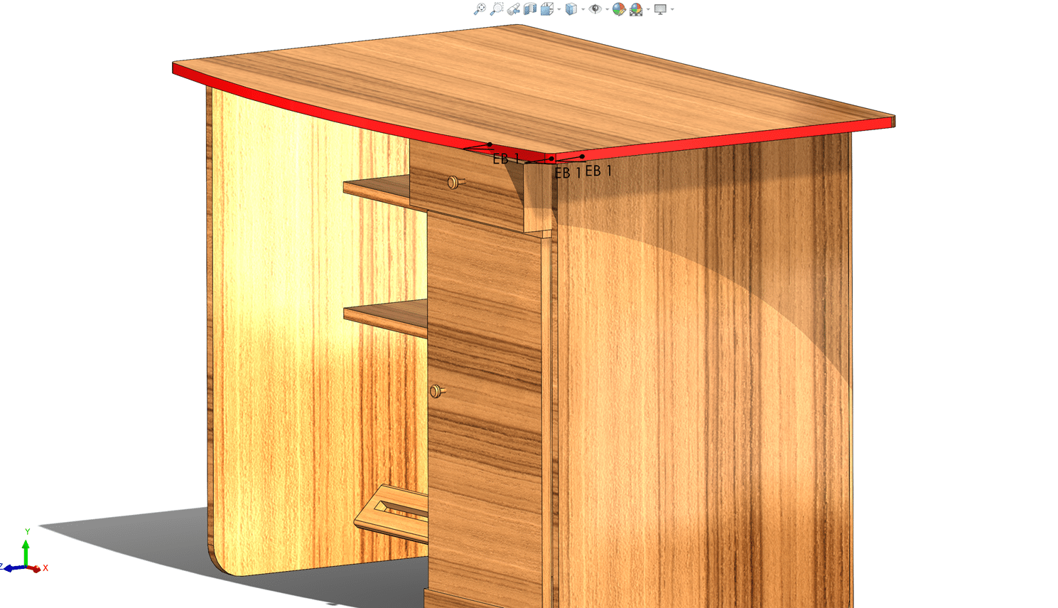
Edge banding is a process of adding a narrow strip at the edges for durable and good-looking trim edges. This is used to cover the exposed edges of wood materials. This process can be done in EdgeWorks within a few mouse clicks, and marked edges will be shown in the printed report.
Edge banding can be removed by just one click using the Roll Back option.
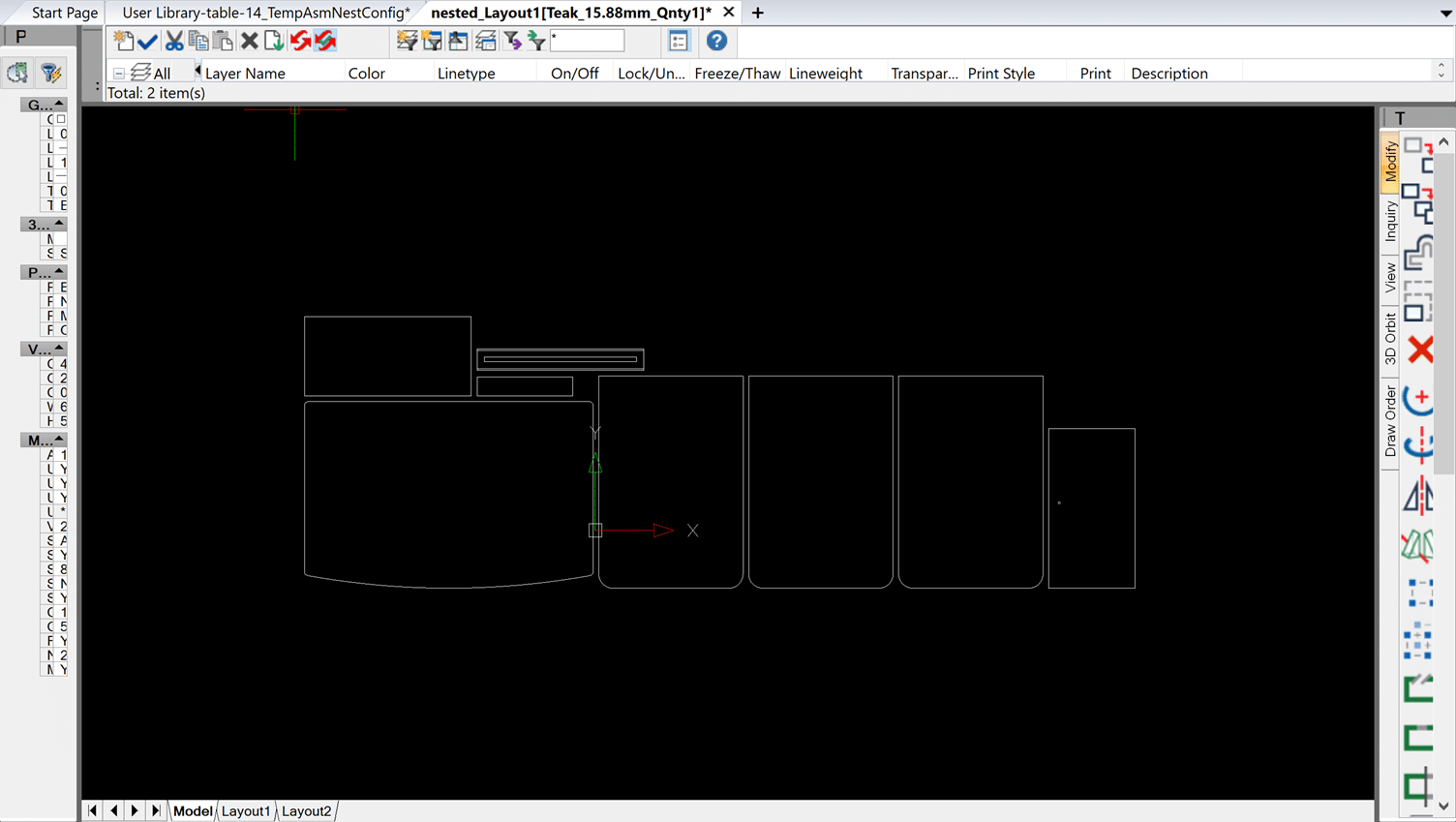
Save as DXF
The Save as DXF option is used to save each layout or assembly into individual DXFs. This will save a lot of time while processing the parts into DXF files.
Generate Report
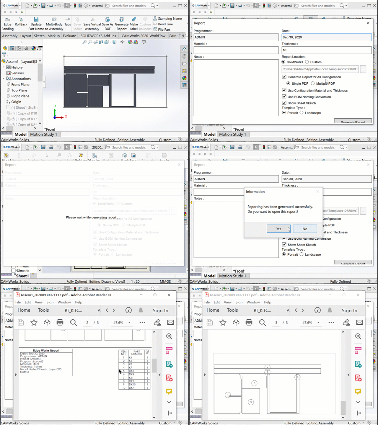
EdgeWorks can generate a report that contains all manufacturing information, including the number of sheets, quantity, part number, item number, material, thickness, sheet size, and edge banding information. This is one of the most useful features in EdgeWorks.
Make Label
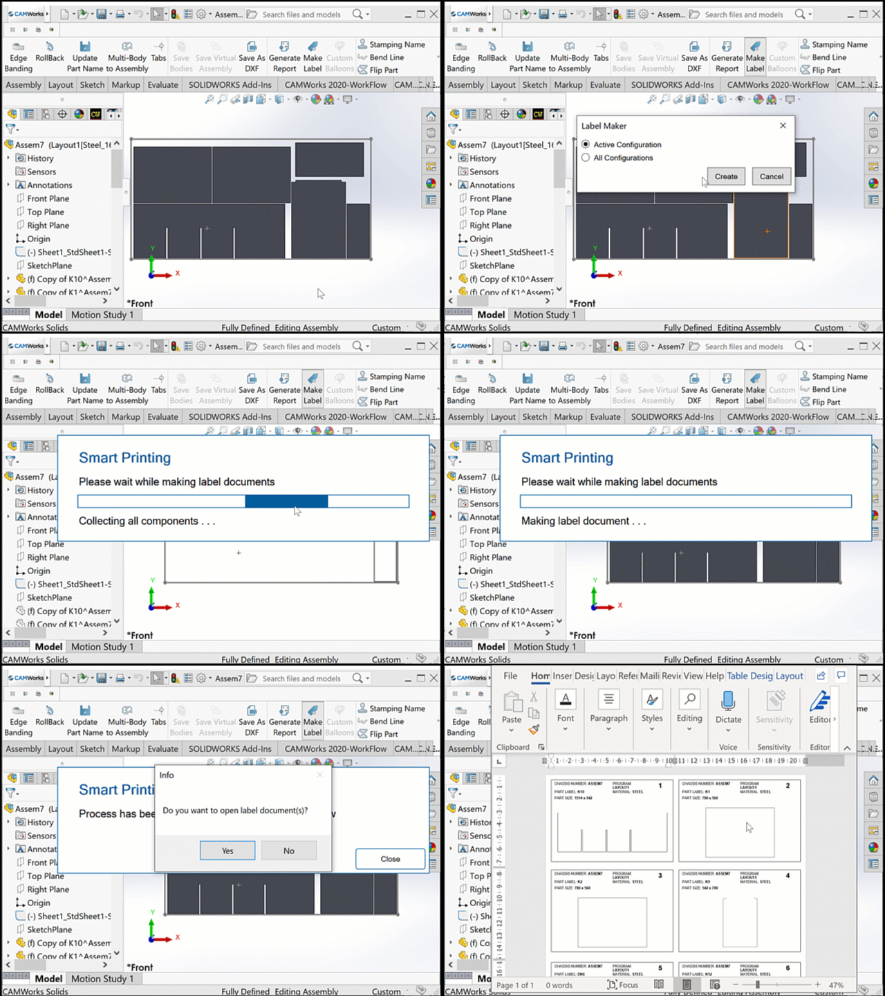
Make Label is a process of making labels for each part of the assembly which contains the part size, material, part name, etc. While clicking on the Make Label icon, it will create and print separate labels for each part and generate a word document with the labels of each part.
Flip and Move Parts
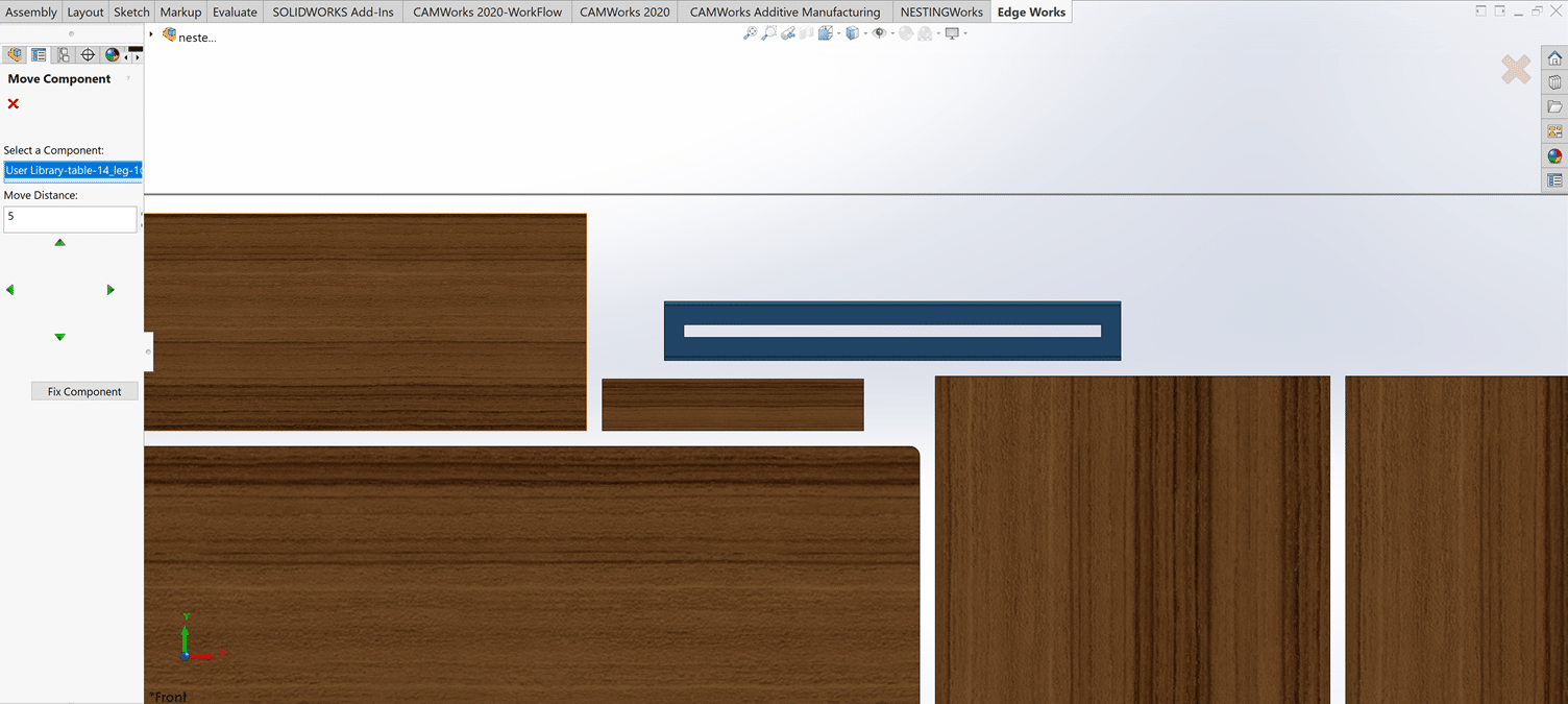
After nesting the parts, if you want to flip some parts because of some machining features on the other side; EdgeWorks helps you flip the selected parts within seconds.
Similarly, we can also move parts by using the move parts option. Move the nested parts by simply typing the amount we want to move or, by using arrows and EdgeWorks, move the parts in any direction.
Stamping Part Names and Bend line
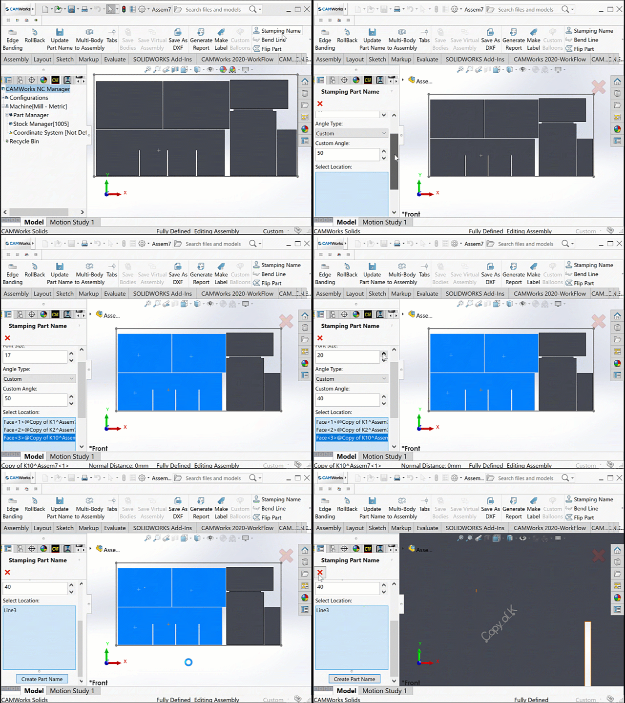
Both stamping part names and bend line options are the engraving process for identification purposes. The stamping part names option creates part names on the top of the part by selecting the parts. We can also edit the angle and font size of the text or name.
The bend line option is generally used to identify and make the bending lines of a sheet metal part visible.
And there are many more options available in EdgeWorks that make the manufacturing process easier and quicker.
Though EdgeWorks is user-friendly and self-explanatory, we are here to help.
For more information on EdgeWorks Software and product enquiries visit us at https://nctools.com.au/ or call us on +61 3 8618 6884


