CAMWorks 5-Axis Module for greater machining productivity
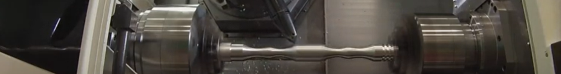
When someone uses the term 5-axis machining, they typically refer to the ability of a CNC machine to move a part or a tool on five different CNC axes at the same time. In addition to the X, Y, and Z axes that are used on 3-axis milling machines, 5-axis machines use two additional rotary axes (A and B). Here are some benefits to using the 5-axis:
- Complex Parts – 5-axis operations allow for the toolpath to cut in areas that cannot be reached using 3-axis milling strategies.
- Minimised setup – Some complex designs and parts require more setups in 3-axis milling. 5-axis operations reduce the number of setups and achieve the required design.
- Better Accuracy – Because of there being fewer setups, there is less chance for error, so better accuracy can be achieved.
- Better Surface Finish – Tool orientation in relation to the machining surface can be optimised for better cutting, which results in better surface finish.
- Longer Tool Life – Because of the ability to tilt the tool in relation to the machining surface, the tool can be tilted to avoid collision with the holder. This results in longer tool life.
Using CAMWorks, we can program 5-axis milling efficiently in lesser time.
The process is simple:
- Define the machine, stock, and fixture of the coordinate system
- Define features using AFR and IFR
- Generate the plan and toolpath
- Simulate and generate the NC code.
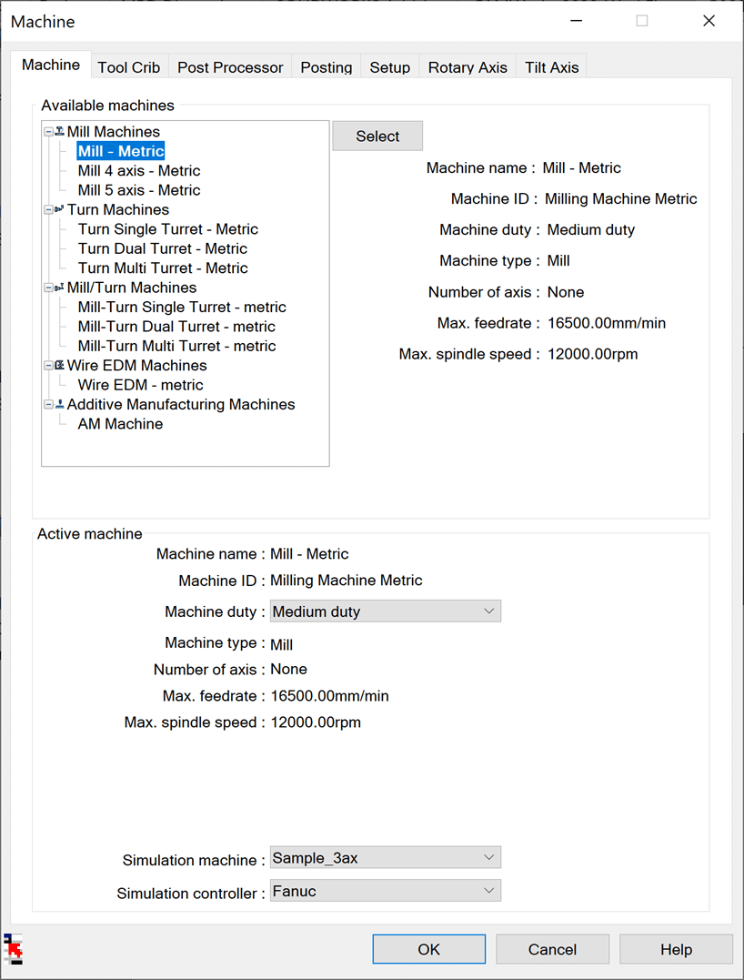
Define the Machine, Stock, and Fixture of the Coordinate System:
The machine definition includes selecting the required machine, tool crib, post-processor, rotary, and tilt axis of the machine.
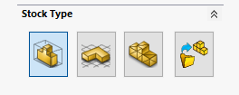
The stock is defined based on which machining is to be done. The fixture of the co-ordinate system must also be defined, which is typically the home point of the machine, where the G-Code is based.
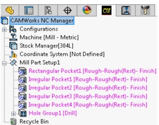
Define Features Using AFR and IFR:
After defining the machine, the stock and FCS extract the machinable features by using either AFR (Automatic feature recognition) or IFR (Interactive feature recognition) or both, as per the requirements.
Define Features Using AFR and IFR:
After defining the machine, the stock and FCS extract the machinable features by using either AFR (Automatic feature recognition) or IFR (Interactive feature recognition) or both, as per the requirements.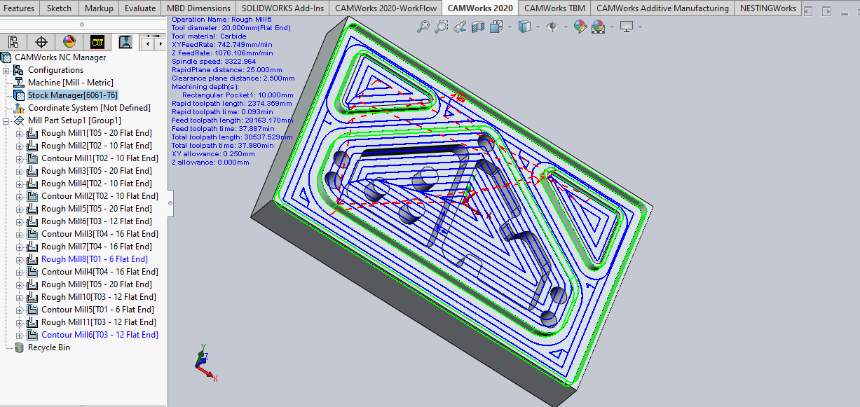
Automatic Feature Recognition (AFR
Interactive Feature Recognition (IFR)
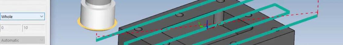
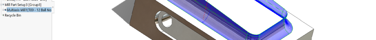
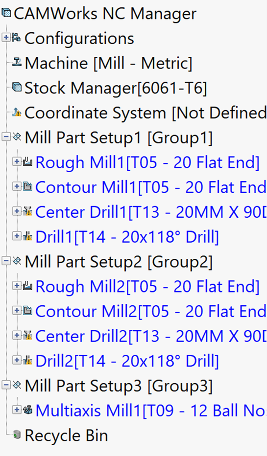
Generate Plan and Toolpath:
Once the features are defined, generate an operational plan and toolpath. You can then edit the parameters of any operation if needed.
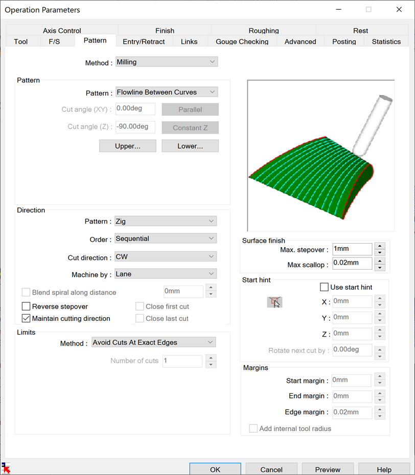
Generate an Operational Plan
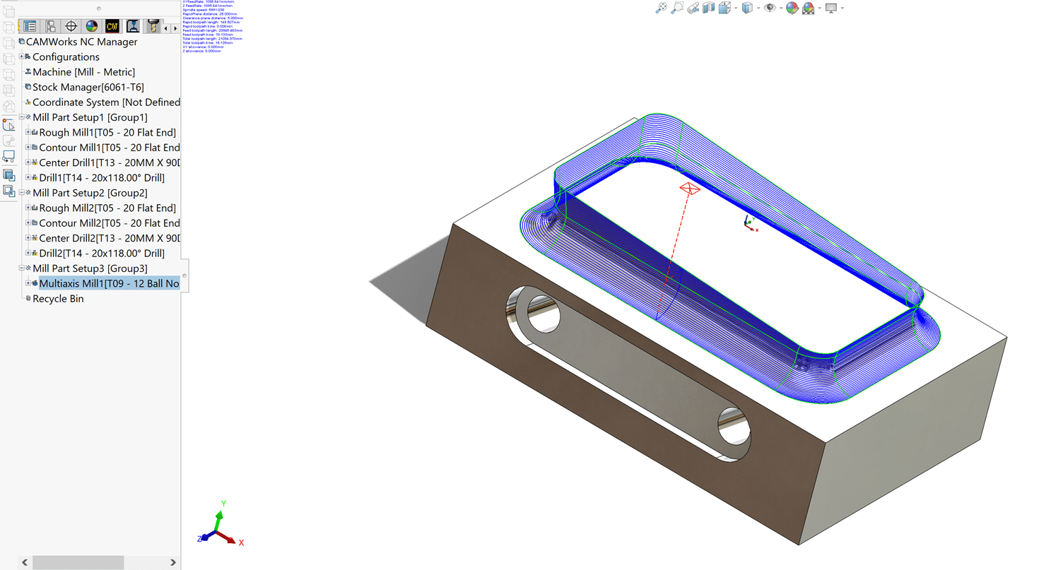
Generate Toolpaths
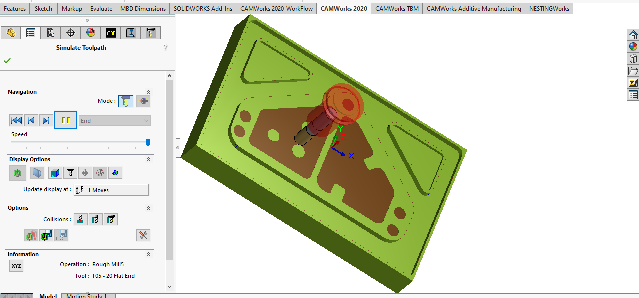
Simulate and Generate the NC code:
Then, simulate the toolpath and generate the NC code if everything seems to be correct.
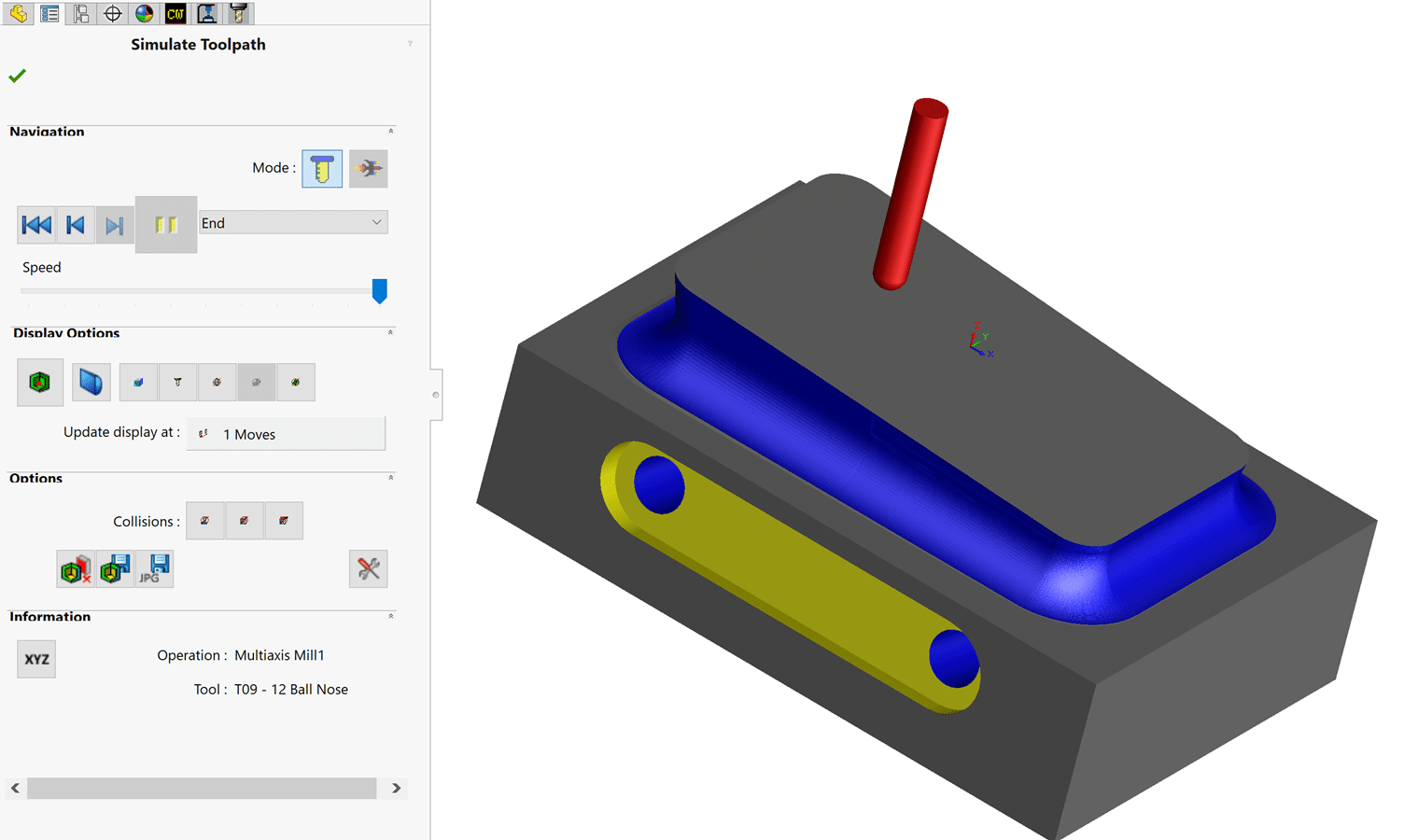
Simulating the Toolpaths
Though CAMWorks is user-friendly and self-explanatory, we are here to help should you require assistance.
For more information on CAMWorks Software and product enquiries visit us at http://www.nctools.com.au/or call us on +61 3 8618 6884.