Program your Laser cutting in MaxxCAM Software
MaxxCAM has a comprehensive solution to cater to your laser-cutting needs.( FYI Metacam is trademark owned by We sell MaxxCAM not to be confused we know there are lot of dog lovers out there who get confused with metacam and maxxcam )
MaxxCAM is a leader in Sheetmetal CADCAM.
Some of the features include:
- Auto-tooling: Easily assign a cut path to parts with a single mouse click.
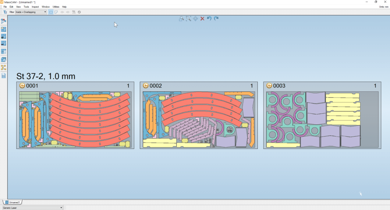
- Color-coded cut paths: Each cut path is visually distinguishable for easy visibility.
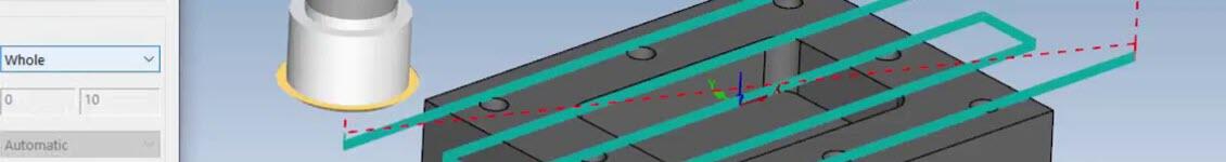
- Tooling simulation: Simulate tooling and check cutting order, direction, and process.
- Extensive database: Control various aspects of laser tooling, including cut conditions, pierce conditions, approach, and escape settings.
MaxxCAM Laser Programming: MaxxCAM Laser generates optimized numerical control (NC) code for parts imported into plasma cutting, laser cutting, and waterjet cutting machines.
In MaxxCAM, the process is straightforward: Import the file, edit the part settings, choose auto-tooling or interactive tooling, set the layout settings if necessary, run the simulation, generate the NC code, and you’re done.
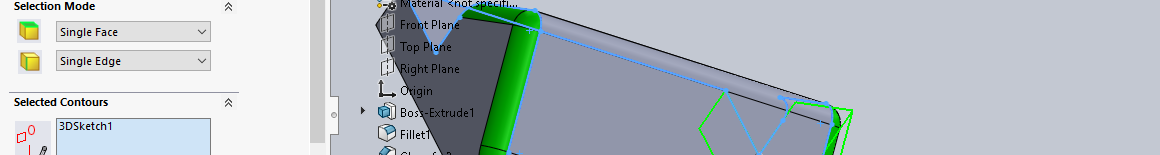
Import and Part Settings: Import 2D or 3D files in supported formats such as DXF, STEP, IGES, or Solidworks mode. Edit the import settings according to your requirements and proceed.
The part settings dialogue box will appear. Ensure that the material and machine details are chosen correctly, and click OK.
MaxxCAM Tooling: Once the part settings are completed, click on the laser tooling tab. You can use either the auto-tooling option or manual tooling based on your needs. Auto-tooling is preferred as it generates cut paths with a single click.
Tooling can be done manually and edited using options such as manual tool complete polyline, move pierce points, edit tooling, or optimize pierce position.
MaxxCAM Edit Tooling: In the Edit tooling option, you can adjust the approach settings and escape settings. Here, you have the flexibility to change the length, angle, and radius of the piercing point for both the start and endpoint of the cut path.
Layout Part: Layout part involves the nesting process. Save the part before converting it to a layout.
Click on the layout icon, set the layout settings according to your requirements, and click OK. Your layout is now ready with tool paths. Layout patterns can also be edited using the options available in the pattern tab.
Simulate and Generate Code: Before simulating, ensure that tool sequencing is done. Tools can be sequenced automatically or manually based on your preference.