What Makes CAMWorks Different
CAMWorks software-CAMWorks is a parametric, feature-based machining software. It enables the integration of design and manufacturing processes in one application. As a result of this integration, users can use the same interface to design and later to simulate machining. CAMWorks provides 2.5 & 3-axis CNC milling and 2-axis CNC lathe programming solutions as well as support for configurations, parts, and assembly machining workflows. CAMWorks’ Model-Based Definition (MBD) and Knowledge-Based Machining technologies can transform your design-to-manufacturing processes by improving communication, reducing errors, and reducing cycle times.
Benefits:
- Simplifies collaboration by providing a single design and programming environment that facilitates the transition from CAD to CAM.
- Concurrent development allows companies to perform tasks sooner, find problems earlier, and make changes more cost-effectively.
- Rules-based machining enables new users to easily adapt to a company’s machining process.
- Tolerance-based machining allows for the best machining strategy and quick adaptation as designs, materials, and tolerances change.
- Feature Recognition allows you to define machinable features within the CAD/CAM environment.
- High-speed machining produces toolpaths that result in shorter cycle times while extending tool life and reducing machine wear.
- The NC Editor makes the verification of G-code simple and straightforward. Additionally, users may back plot the G-code for review and then send the file directly to the CNC control using DNC capabilities.
- The communication between programming and setup is facilitated by toolpaths output inside eDrawings. Operators can view the 3D model and associated toolpaths to understand the machining process.
- Using SOLIDWORKS assemblies, it is possible to visualize fixtures and tooling. Once fixtures are designed, CAMWORKS can automatically adjust toolpaths to avoid colliding with the designed components.
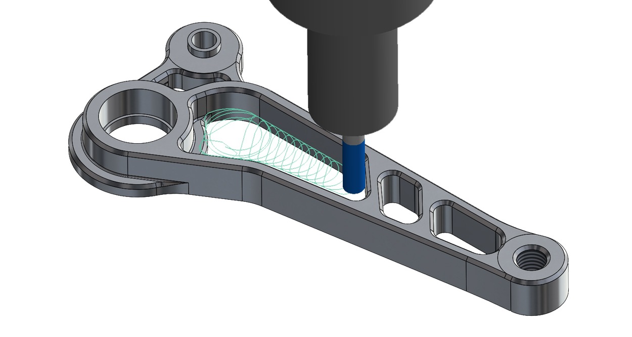
- Toolpath Simulation within CAMWORKS will allow you to verify the correct machining strategy and setup information for each component produced.
The CAMWORKS process can be explained as follows.
The following diagram illustrates the steps involved in creating machining simulations in CAMWorks.
Create Design Model
- Creating a solid model, part, or assembly in CAMWORKS
Choose NC Machine
- Select an NC machine, mill, or lathe intended to be used for the machining operations, select a tool crib, select a suitable post-processor, and determine a coordinate system
- Create stock, including size, shape, and material
Extract or Create Machinable Features
- Using AFR to extract machinable features embedded in a solid model, such as holes, packets, bosses, etc.; or by manually creating machinable features
Generate Operation Plan
- CAMWorks creates an operation plan, which includes machining strategies, cutting tools, and machining parameters, such as feed rate, spindle speed, stepover, depth of cut, etc.
Generate Toolpath
- CAMWorks generates the toolpath for each operation.
Simulate Toolpath
- Simulate machining operations using material removal simulation capability or step through toolpath
- Record machining time
Post Process
- Convert toolpath to G-code
- Verify G-code