
Multi Axis operations with CAMWorks – Port Machining
Port Machining is a common strategy with 5 axis machining to machine the inside of an intake or exhaust channels and other ports. In this blog, we will see the procedure to set this up. This can be done quickly with greater accuracy. The first step is to display the port Surface in the Surface bodies folder in SOLIDWORKS and hide the solid body of the part. A surface body has already been modelled for this part. We will be using this surface to create the finishing toolpath.  Create a new multisurface feature, selecting Faces or Surfaces as the feature type and strategy, and selecting 5 Axis as the port. Select the required faces and click OK.
 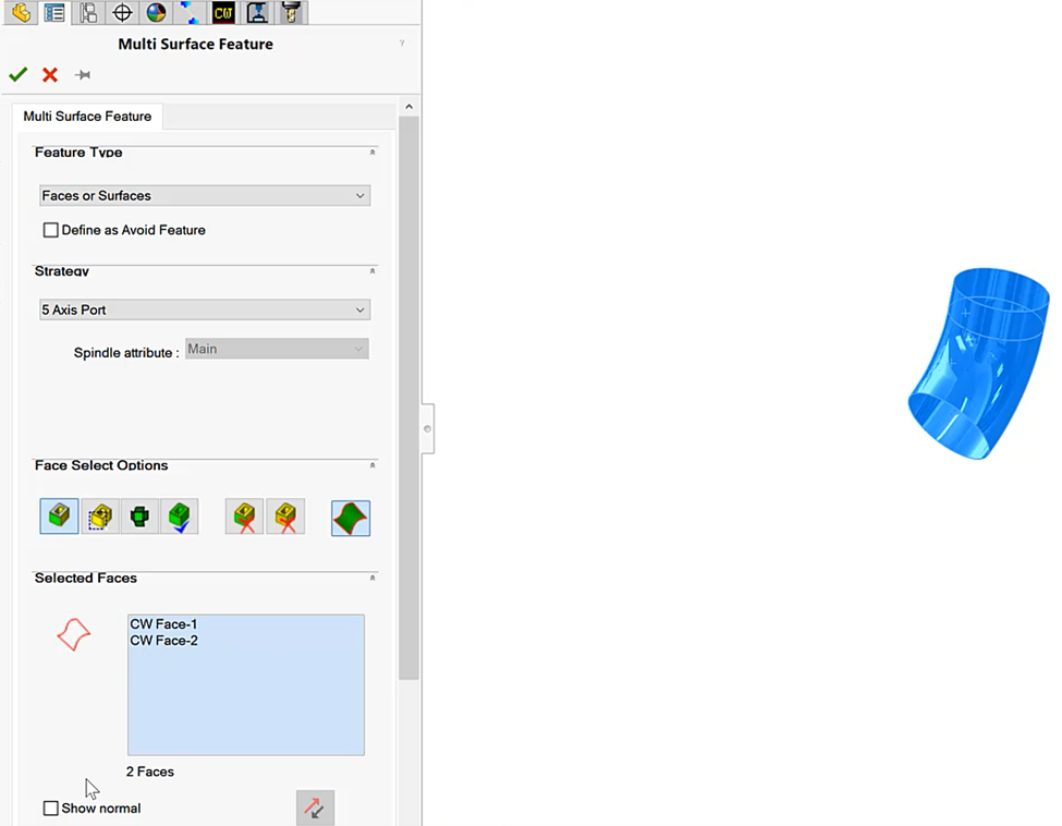 Generate the operational plan and edit the operational parameters based on the desired outcome. This setting will force the tool axis to be coincident with the curve from the start point of the curve, as shown in the preview image in the operation parameters. As the tool moves down the surface, the axis of the tool will remain parallel to the curve until it reaches the endpoint of the curve that coincides with the lower edge curve of the operation.
  Next, the curve will be defined. Selecting the Tilt Curve button will activate the Curve Wizard property manager. We may select either the SOLIDWORKS sketches or existing edges in the model to serve as our Tilt Curve.
  Generate toolpaths and simulate the machining process to see how it is performed.
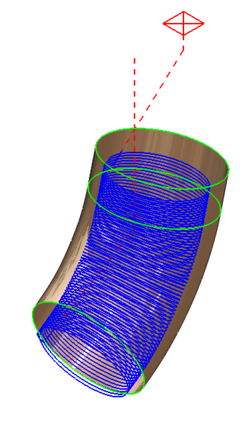
Although CAMWorks is intuitive and straightforward to use, if assistance is required, it can be provided. For more information on CAMWorks Software and product enquiries, visit us at http://www.nctools.com.au/or call us on +61 3 8618 6884.