SOLIDWORKS CAM and CAMWorks: From Setup to G-Code
SOLIDWORKS CAM and CAMWorks: From Setup to G-Code
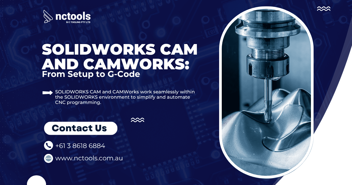
SOLIDWORKS CAM and CAMWorks work seamlessly within the SOLIDWORKS environment to simplify and automate CNC programming. Whether you’re machining basic parts or handling complex geometry, this integrated solution allows users to define setups, generate toolpaths, simulate machining, and post process—all within one platform. This overview walks through the essential steps of the workflow, highlighting how to get from CAD model to G-code with accuracy and efficiency.
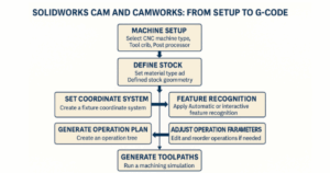
- Machine Setup
Select the type of CNC machine (Mill, Turn, Mill-Turn, EDM) under the Machine tab.
- Tool Crib: Choose or customize tools with defined parameters.
- Post Processor: Pick the correct .CTL file for your machine.
- Posting Settings: Configure options like coolant control, tool offsets, and probing.
- Define Stock
Set material from the CAMWorks or SOLIDWORKS CAM library to influence feeds and speeds.
Define stock as a box, cylinder, extrusion, or custom shape. Stock geometry supports operations like rest machining and defines limits for 2.5D and 3-axis strategies. - Set Coordinate System
Create a user-defined Fixture Coordinate System.
Use part or stock bounding boxes to automatically set the origin.
Align axes and choose the machining face based on your setup. - Feature Recognition
Use Automatic Feature Recognition (AFR) to detect standard features like holes, pockets, bosses, and slots.
For full control or more complex parts, use Interactive Feature Recognition (IFR) to manually define features. - Generate Operation Plan
Based on recognised features and database settings, SOLIDWORKS CAM/CAMWorks creates the Operation Tree.
It selects tools and machining strategies according to predefined rules. - Adjust Operation Parameters
Right-click operations to edit parameters such as speeds, feeds, depth of cut, or tool selection.
You can also rearrange the sequence of operations if required. - Generate Toolpaths
Once operations are defined, generate toolpaths directly on the SOLIDWORKS model.
Adjust strategies for climb or conventional milling as needed. - Simulate Toolpaths
Simulate machining to visualise material removal and verify each operation.
This helps catch setup errors or toolpath issues before running on the machine. - Post Process to G-Code
Post processing translates operations into NC code for your specific machine.
SOLIDWORKS CAM and CAMWorks generate a G-code file and a .SET file.
Use the NC Editor to view, edit, or send code directly to your CNC via serial communication.
Back plotting is available for added verification.
For more information on CAMWorks Software and product enquiries visit us at https://nctools.com.au/ or call us on +61 3 8618 6884